![]()
![]()
![]()
![]()
![]()
![]()
|
|
|
|
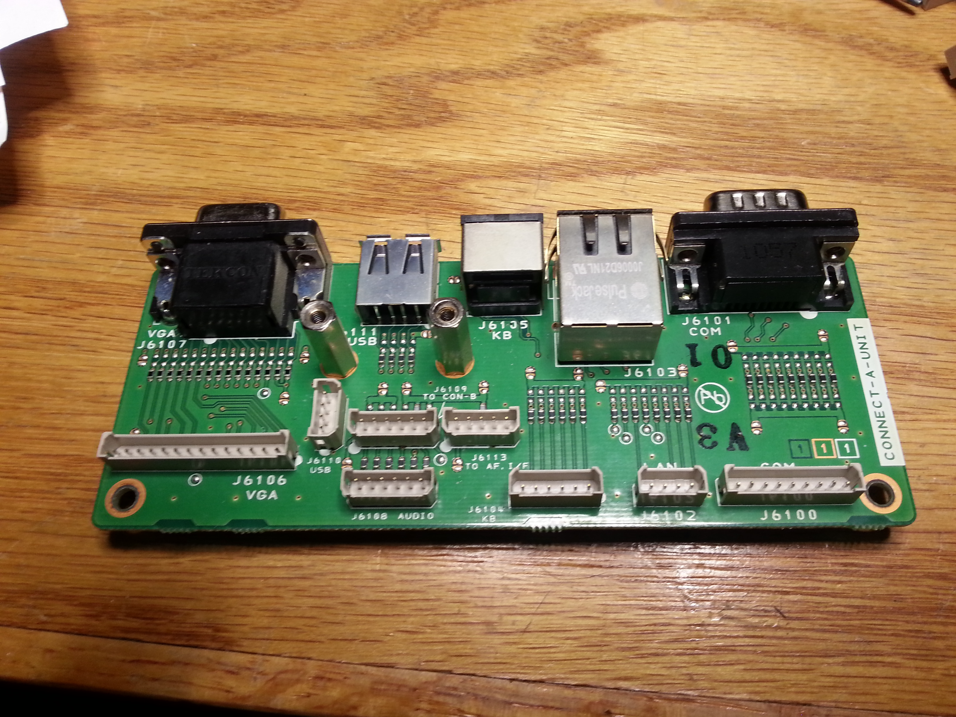
This page is descibes the differences between the DMU 2000 technical manual and the current DMU. I have incorporated the updated schematics and some FT-2000 schematics in an updated manual. In the technical manual it shows multiple I/O connectors between the Connect A board and CPU board, J6102 & J6106 are now ribbon connectors to the PC board.
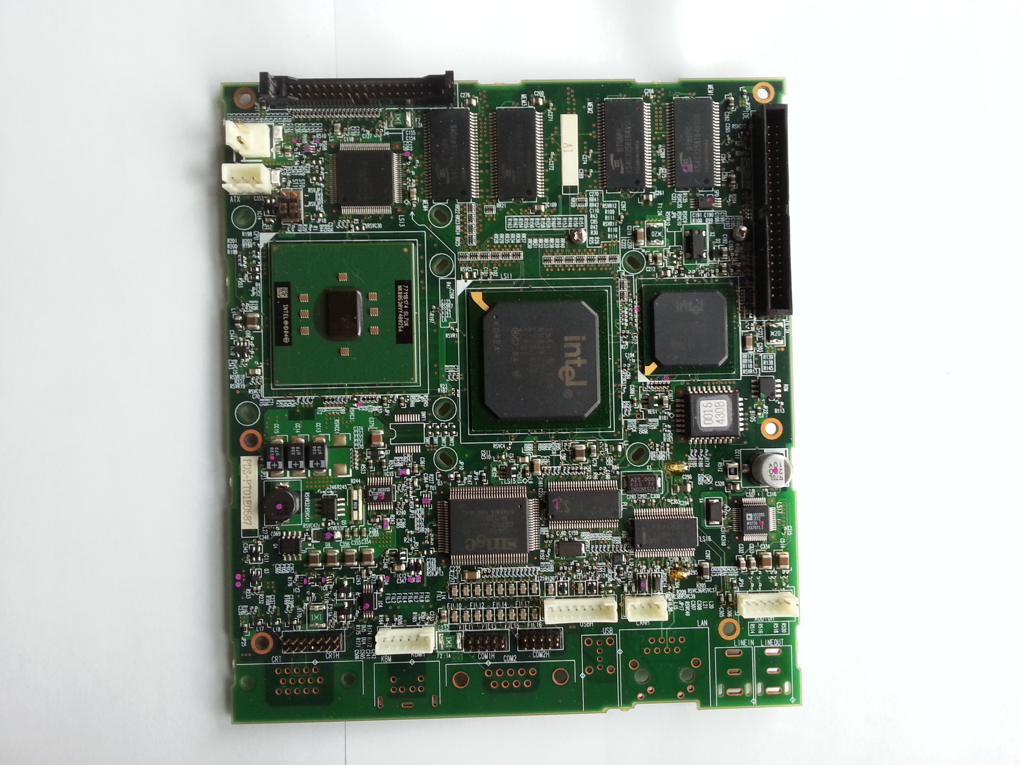
Click to enlarge image The next set of pictures show how the current board is laid out.
Click to enlace image. The following is the updated schematics of the old and new. In the new circuit the radio receives data from Audio out Left on pin 2, it also shares it with audio out on back panel.
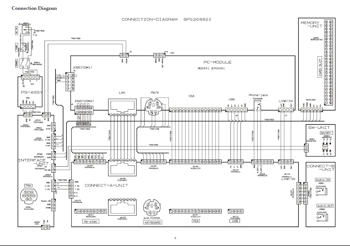
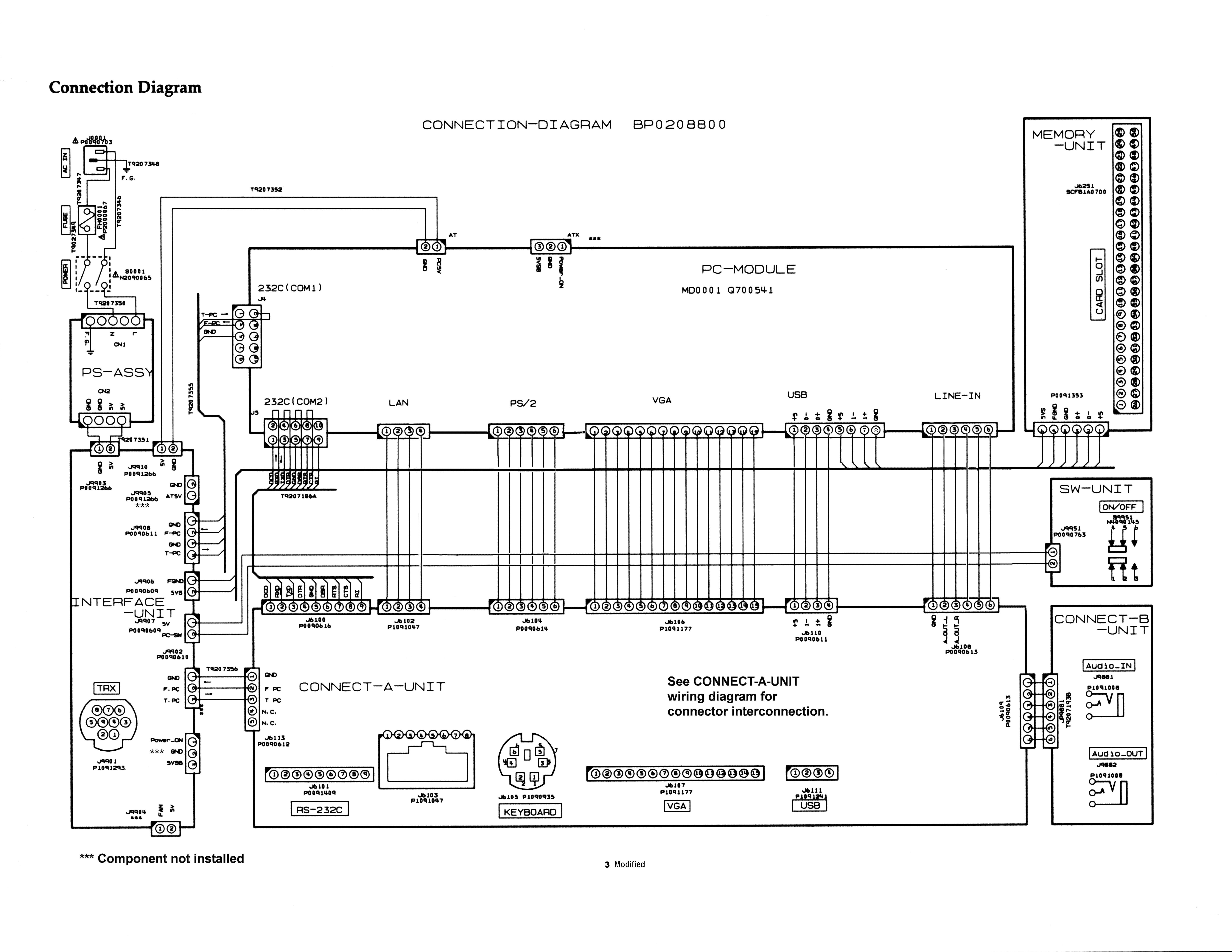
The following is the interconnection diagram for the old style and new style. J6112 is not in the new version, J6113 and J6109 are combined and go out J6108 to Line in on the PC board.
The following is the DMU radio interface. I did not modify
the schematic since there were no changes. The board does not contain all
the components as can be seen.
The following are the Audio in and out Jacks on the back of the DMU. The audio out is unchanged with the exception that it shares Pin 2 audio out left with the radio. Audio in has a different configuration, there is no connection to Pin 6 while Pin 5 is audio in right channel. Audio in is from the radio audio out jack and is used by the DMU for audio scope displays.
One final change was on the DMU memory unit, the front CF card reader. The LED does not go to ground as shown in the original circuit but is driven by a transistor from Pin 6 of J6250, this comes from the Interface unit J9906.When the radio is on and the PC is on with the front power switch pushed in, the LED will be able to turn on. The other part of the connector goes to USB on the PC board.
The following images show some of the interconnections.
Here is a basic explanation of the DMUs operation. The DMU boots up like any PC when the back power switch is turned on. Assuming the radio is on, when you push the front power switch it sends a signal to the radio that it is on and to send data. The radio sends commands to the DMU through the Interface unit to Com 1 on the PC board, at the same time it sends out audio data to the Left Channel In on the PC board. It also receives audio from the Left Channel Out of the PC. The PC is a simple Micro PC with a very slow Celeron processor, a few megs of memory and a CF, compact flash, card for a disk drive. I have started to think about using the interface out of the radio but use a more powerful PC, see my Wyse RxOL page. This is all for now, I hope it was of some help. 73
| ||||||||||||||||||||||||||||||||||||||||||||||||||||||||||||||||||||||||||||||||||||||||||||||||||||