 Display Assembly
Dell™ Studio 1535/1536/1537 Service Manual

|
CAUTION: Before you begin the following procedure, follow the safety instructions that shipped with your computer. |
|
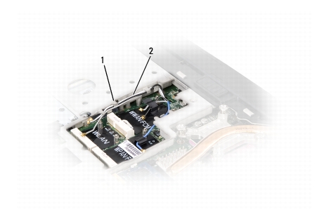
1 |
securing tabs |
2 |
antenna cables |
|
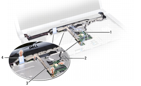
1 |
antenna cables |
2 |
display power cable |
|
3 |
camera cable |
4 |
display data cable |
|
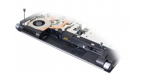
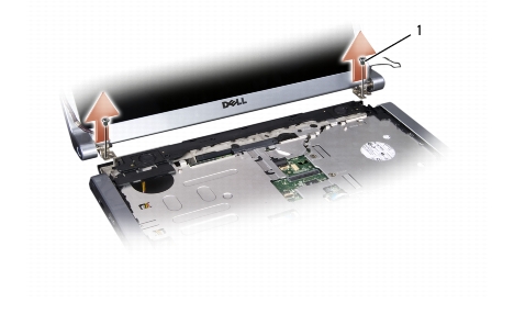
1 |
hinge screws (2) |
|
|
CAUTION: Before you begin the following procedure, follow the safety instructions that shipped with your computer. |

|
NOTE: Ensure that the display and camera cables are properly routed and secured beneath the plastic tabs. |
|
|
CAUTION: Before you begin the following procedure, follow the safety instructions that shipped with your computer. |
|
|
CAUTION: The following instructions are not applicable to Edge-to-Edge display panels, which should not be disassembled. |

|
NOTICE: Removal of the bezel from the display bottom cover requires extreme care to avoid damage to the bezel and the display panel. |
|
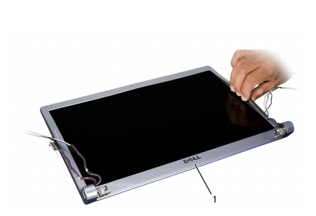
1 |
display bezel |
|
|
NOTE: In some computers, the display bezel might have double-sided tape on both ends. To reuse the tape, carefully remove the bezel. |
|
|
CAUTION: Before you begin the following procedure, follow the safety instructions that shipped with your computer. |
|
|
CAUTION: Before you begin the following procedure, follow the safety instructions that shipped with your computer. |
|
|
CAUTION: The following instructions are not applicable to Edge-to-Edge display panels, which should not be disassembled. |
|
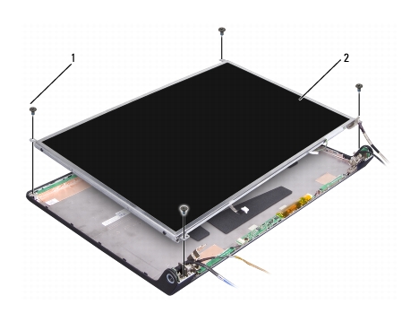
1 |
screws (4) |
2 |
display panel |
|
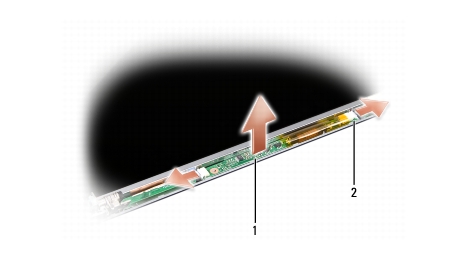
1 |
inverter |
2 |
connectors (2) |
|
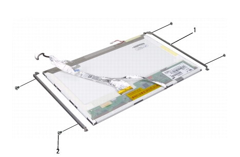
1 |
display panel bracket (2) |
2 |
screws (4) |
|
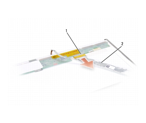
1 |
display cable connector |
2 |
display cable |
|
|
CAUTION: Before you begin the following procedure, follow the safety instructions that shipped with your computer. |
|
|
CAUTION: Before you begin the following procedure, follow the safety instructions that shipped with your computer. |

|
1 |
inverter |
2 |
connectors (2) |
|
|
CAUTION: Before you begin the following procedure, follow the safety instructions that shipped with your computer. |
|
|
CAUTION: Before you begin the following procedure, follow the safety instructions that shipped with your computer. |
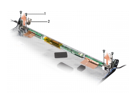
1 screws (4) 2 hinges (2)
|
|
CAUTION: Before you begin the following procedure, follow the safety instructions that shipped with your computer. |