
Dell™ Studio 1535/1536/1537 Service Manual
|
|
CAUTION: Before you begin any of the procedures in this section, follow the safety instructions that shipped with your computer. |

|
NOTICE: To help prevent damage to the system board, you must remove the battery from the battery bay before you begin working inside the computer. |
Your computer supports three Mini-Card slots:

|
NOTE: Depending on the configuration of your system, one or more of the Mini-Cards might not be present. |
The types of Mini-Cards supported are:
|
|
NOTE: Your computer can only support two Full Mini-Cards and one Half Mini-Card at a time. |
|
|
NOTE: The WLAN slot supports a half Mini-Card. |
|
|
NOTICE: When you disconnect a cable, pull on its connector or on its pull-tab, not on the cable itself. Some cables have connectors with locking tabs; if you are disconnecting this type of cable, press in on the locking tabs before you disconnect the cable. As you pull connectors apart, keep them evenly aligned to avoid bending any connector pins. Also, before you connect a cable, ensure that both connectors are correctly oriented and aligned. |
|
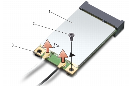
1 |
WWAN/WLAN Mini-Card |
2 |
M2 x 3-mm securing screw |
3 |
antenna cable connectors (2) |
|
|
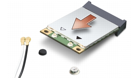
NOTE: If you are removing a WPAN/UWB Mini-Card, disconnect the blue antenna cable from the Mini-Card. |
|
|
NOTICE: When the Mini-Card is not in the computer, store it in protective antistatic packaging. For more information, see "Protecting Against Electrostatic Discharge" in the safety information that shipped with your computer. |
|
|
NOTICE: Install the UWB Mini-Card in the WWAN or WPAN slot. Do not install a UWB Mini-Card in the WLAN card slot. Doing so may cause damage to your computer. |
|
|
NOTICE: Use firm and even pressure to slide the card into place. If you use excessive force, you may damage the connector. |
Connectors on the Mini-Card | Antenna Cable Color Scheme |
|---|---|
WWAN (2 antenna cables) Main WWAN (white triangle) Auxiliary WWAN (black triangle) |
white with gray stripe black with gray stripe |
WLAN (2 or 3 antenna cables) Main WLAN (white triangle) Auxiliary WLAN (black triangle) MIMO WLAN (*gray triangle) |
white black gray |
WPAN (one antenna cable) WPAN |
blue |
* The MIMO WLAN is optional and may not be available in all computers. | |
|
|
NOTE: The gray antenna cable may not be available in all computers. The presence of the gray antenna cable in your Mini-Card compartment depends upon the type of display. |
|
|
NOTE: If you are installing a communication card from a source other than Dell, you must install the appropriate drivers and utilities. For more information, see the Dell Technology Guide. |